Creating Gauge Interface Connections
Using this procedure, you will create the gauge interface connection.
- Select Access Menu and then select Data Collection | Gauge Devices.
-
In the Gauge Devices landing page, select Create Interface Connection.
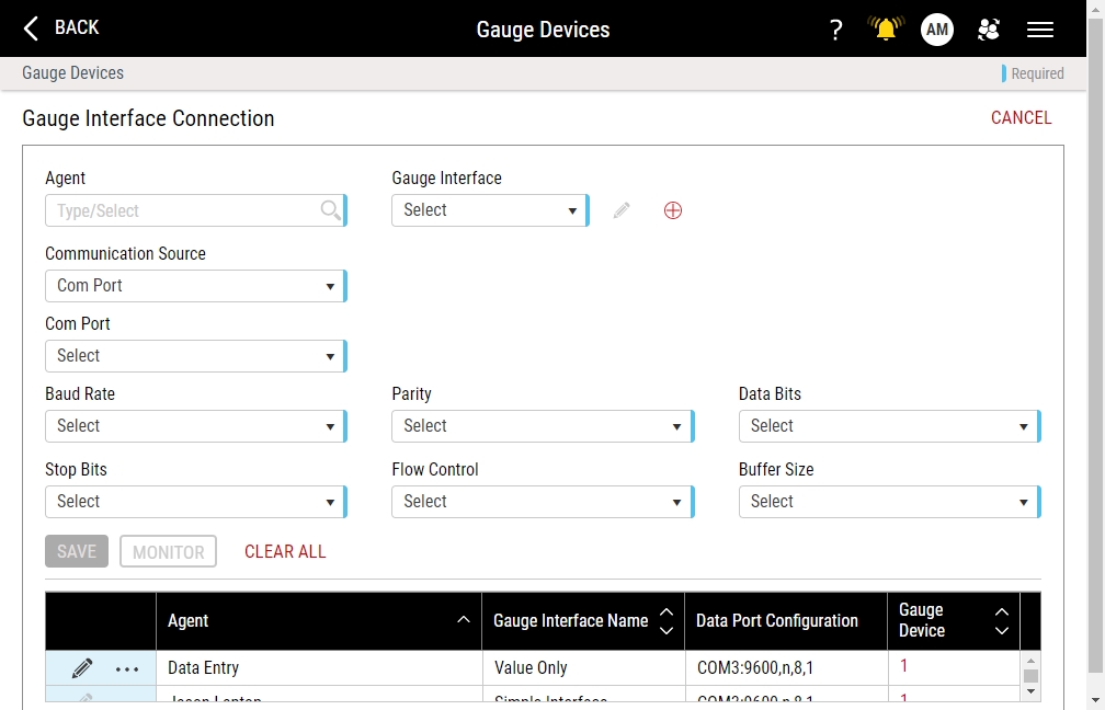
- In the Agent drop-down list, select the desired gauge agent. Hint

-
In the Gauge Interface drop-down list, select the desired interface.
To create a new gauge interface, select Add, and fill out the Create Gauge Interface page. For more information, please see Creating Gauge Interfaces.
-
To configure your communication information, do the following:
-
Serial Connection
- In the Communication Source drop-down list, select Com Port.
- In the Com Port drop-down list, select the port number of your serial device.
- In the Baud Rate drop-down list, select the desired transmission speed.
- In the Stop Bits data field, select the interval (in bit-time) for Enact to remain idle between bytes transmissions. If Enact receives a new byte before the end of the stop bit, the new byte is marked as an error.
- In the Parity drop-down list, select the parity bit value, which is used as a rudimentary check digit to identify errors in a byte.
-
In the Flow Control data field, select the flow control (or handshaking) between the transmitter and receiver:
- None. There is no flow control between the transmitter and receiver, and the transmitter can send data whenever it is ready.
- XON/XOFF. The receiver can send a wait/don't wait command to the transmitter.
- CTS/RTS. The receiver can send a wait/don't wait command using voltage through a wire that is connected to the transmitter.
- RTS=off/DTR=on. The flow control combines both CTS/RTS and XON/XOFF.
- In the Data Bits drop-down list, select the expected number of bits in the transmitted byte.
-
In the Buffer Size data field, select the serial port buffer value. Used in high speed communications, Enact buffers first-in-first-out (FIFO) data to ensure no bytes are lost during transmission.
InfinityQS recommends selecting a 128-byte buffer.
-
TCP/IP Connection
- In the Communication Source drop-down list, select TCP/IP.
-
Under the Communication Source data field, select the radio button of the desired connection method:
- IP Address. Type the IP address and the communication port.
- Host. Type the host server name and communication port.
-
-
To test the gauge interface connection, do the following:
-
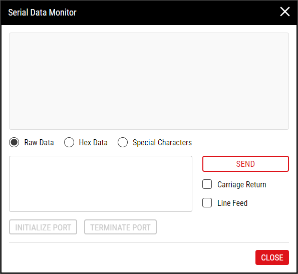
Select Monitor. The Serial Data Monitor opens.
-
On your connected device, press SEND or DATA. The raw data value appears in the upper text box.
To see the value as hexadecimal data, select Hex Data.
To see the value including all special characters, select Special Characters.
-
To send values to your connected device, type the desired value in the lower text box, and then select Send.
To include a carriage return with the sent value, select Carriage Return.
To include a line feed with the sent value, select Line Feed.
- To initialize the port, select Initialize Port.
- To terminate the port, select Terminate Port.
- Select OK.
-
- Select Save.

