The Mux (or multiplexer) Device Provider reads data through the InfinityQS mux device from multiple measuring devices, such as micrometers and calipers, attached to a single workstation. The Mux Provider can de-multiplex (or disassemble) data from the different measuring devices, publishing readings from each gauge independently.
When adding or modifying a Mux Device Provider, the Configuration (Mux Device Providers) dialog box opens.
-
To configure the Mux Device Provider, do the following:
-
 Identification Section
In the identification section, you can set the unique name, the provider group, and device state.
- In the Server Name data field, type the Bridge Provider identification name using a maximum of 32 characters. Ensure the name is unique and descriptive.
- In the Group data field, type the group name.
- In the Device State drop-down list, click the desired state (Disabled or Enabled).
-
Connection Settings Section
In the Connection Settings data field, you can configure the provider connection, which interfaces directly with hardware, files, or software products. To configure the connection, click the ellipsis button (...), and then do the following:
-
Click the desired source in the Source drop-down list:
-
Serial Port
Serial ports (RS232 or RS422) are a common and inexpensive way of connecting your measurement devices to your computer, either directly or through mapping from other computers. The serial port notation follows the standard of [baud], [parity], [data bits], [stop bits], [flow control], so the serial port setting 9600,n,8,1,n indicates 9600 baud rate, no parity, 8 data bits, 1 stop bit, and no handshaking.
- In the Serial Port drop-down list, click the port number of your serial device (DMS only displays mapped ports).
- In the Baud Rate drop-down list, click the desired transmission speed (DMS only displays valid baud rates).
- In the Parity drop-down list, click the parity bit value, which DMS uses as a rudimentary check digit to identify errors in a byte.
- In the Data Bits drop-down list, click the expected number of bits in the transmitted byte.
- In the Stop Bits drop-down list, click the interval (in bit-time) for the DMS to remain idle between bytes transmissions. If the DMS receives a new byte before the end of the stop bit, the new byte is marked as an error.
-
In the Flow Control drop-down list, click the flow control (or handshaking) between the transmitter and receiver:
- None. There is no flow control between the transmitter and receiver, and the transmitter can send data whenever it is ready.
- XON/XOFF. The receiver can send a wait/don't wait command to the transmitter.
- CTS/RTS. The receiver can send a wait/don't wait command using voltage through a wire that is connected to the transmitter.
- RTS and XON/XOFF. The flow control combines both CTS/RTS and XON/XOFF.
If the DMS shows no data collection while the measurement device transmits, change the flow control to a new setting and try again.
-
In the Input Buffer Size drop-down list, click the serial port buffer value, which is used in high speed communications to buffer first-in-first-out (FIFO) data to ensure no bytes are lost during transmission.
InfinityQS recommends selecting a 128-byte buffer.
- In the Idle Reset (Minutes) data field, type the duration of inactivity (in minutes) that would cause the provider to switch to an idle state, which DMS uses for hardware that does not support the Keep Alive setting or for serial port connections.
-
In the Raw Data Output section, you can examine the generated data.
- To view non-visible characters (for example, <10> for line feed or <13> for carriage return), click the Translate Non-Visible checkbox.
- To clear the contents, click the Clear button.
-
Ethernet TCP/IP
With TCP/IP, you can easily collect data from network-ready devices over longer distances without the need for specialized servers or wiring. In fact, you can collect data from anywhere in your network, even if the DMS runs in the United States and the measurement devices reside in China.
-
In the IP Address data field, type the desired computer name on your local network, web address, or IP address from a local or remote network.
Be sure to use computer names, web addresses, or IP addresses that are approved by your IT or network administrators. If they start seeing unexpected traffic, they may kill access to the target.
-
In the IP Port data field, type the desired port, which is a value between 1 and 65535.
All network-ready devices listen on specific ports, which are similar to telephone extensions. You must provide the device's port number (or extension) that the DMS uses to connect. For more information about ports your device accepts connections on, see the device's user manual.
- In the Keep Alive (sec) data field, type the duration (in seconds) that the DMS should remain connected to the device.
- In the Idle Reset (Minutes) data field, type the duration of inactivity (in minutes) that would cause the provider to switch to an idle state, which DMS uses for hardware that does not support the Keep Alive setting or for serial port connections.
-
To test the connection of the IP Address and Port, click the Connect button.
-
Success. DMS displays the raw data in the Raw Data Output section. To view non-visible characters (for example, <10> for line feed or <13> for carriage return), click the Translate Non-Visible checkbox.
-
Fail. DMS displays an error message with the red background.
To clear the contents, click the Clear button.
-
-
-
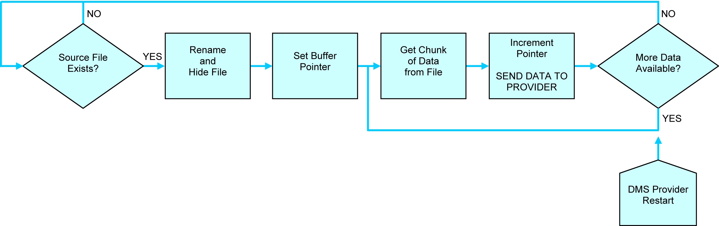
File
Because DMS treats a file as just another serial stream of data, you can easily import data without programming. When aware of a new file, DMS immediately renames and hides the file, and then processes the file in incremental blocks as applicable based on the record size and the setting of the Buffer Size data field, marking each point in the file that has been completed. Once finished, DMS deletes the file and searches for another file.
-
In the Specify Filename data field, click the ellipsis button (...), browse to and click the desired file, and then click the Open button.
DMS supports wildcards (*) in the data filename, allowing you to type C:\DataStorage\*.txt to collect all text files in the DataStorage folder. To strip out quote delimiters from incoming data, click the CSV checkbox.
- In the Encoding drop-down list, click the character encoding in the data file (for example, ASCII, Unicode, UTF-8, UTF-7, UTF-32, or Big Endian Unicode). If you are unsure about the character encoding, click Default.
- In the Buffer Size drop-down list, click the buffer value. To avoid consuming large amount of memory during file processing, you can set how much of the file (in bytes) that DMS processes per block.
-
In the Raw Data Output section, you can examine the generated data.
- To view non-visible characters (for example, <10> for line feed or <13> for carriage return), click the Translate Non-Visible checkbox.
- To clear the contents, click the Clear button.
-
-
DMS Item
With the DMS Item connection, you can import values directly from the DMS.
-
In the DMS Item Name data field, click the ellipsis button (...), and then do the following:
-
In the Data Type drop-down list, click the desired data type.
Available Data Types
- Value. Any type of data, including string, date/time, or numeric. When setting a DMS tag item as a test value, ensure that the values will always be numeric.
- Time Stamp. Date / time that the DMS tag item value was last updated.
- Reading Number. Counter value that increments by one with each new value published to the DMS.
- Elapsed Time. Time (in seconds) between Time Stamp and Previous Time.
- Unix Time. Time (in seconds) since 12:00:00 January 1, 1970 that the DMS tag item value was last updated.
- Previous Value. DMS tag item value prior to the current DMS tag item value.
- Previous Time. Date / time of the DMS tag item prior to the current DMS tag item value.
- Previous Unix Time. Time (in seconds) since 12:00:00 January 1, 1970 of the DMS tag item prior to the current DMS tag item value.
- In the Server drop-down list, click the desired DMS server, if necessary.
- Click the desired DMS tag item.
- Click the OK button.
-
-
In the Raw Data Output section, you can examine the generated data.
- To view non-visible characters (for example, <10> for line feed or <13> for carriage return), click the Translate Non-Visible checkbox.
- To clear the contents, click the Clear button.
-
-
- Click the OK button.
-
-
Read Command Section
In the Read Command section, you can select the method that your mux device handles read requests from an SPC client.
- Perform Individual Channel Reads. Reads one channel from the mux device, used with a multi-channel mux device connected to a single instrument. If you use a global read with a single instrument, the provider will idle as it tries to read all the other channels, greatly delaying the data return to the DMS.
- Perform Global (ALL) Channel Reads. Requests a read on all channels when the SPC client invokes a read on any channel, used when measurements from several connected devices are interrelated.
-
Raw Data Sampling Section
In the Raw Data Sampling section, you can examine the generated data.
- To view non-visible characters (for example, <10> for line feed or <13> for carriage return), click the Translate Non-Visible checkbox.
- To clear the contents, click the Clear button.
-
Data Items Section
In the Data Items section, you can configure the channels that send data, enabling automatic channel selection and enabling Minimum, Maximum, and TIR tracking.
- Automatic Channel Selection. When you are unsure which channels will send data, the Mux Provider will automatically select channels that send data.
- Channel #. Use the selected channel, which automatically creates a DMS item for it.
- Min, Max, TIR. Track Minimum, Maximum, and TIR values under the selected channel, if supported by the Mux device.
-
- Click the OK button.