Descriptors (Slicing)
Parts
- Select Access Menu and then select Part | Parts.
-
To add the Chips - Uncooked part, select Create Part, and then do the following:
- Short Name: Chips - Uncooked
-
Image: ChipsUncooked.png
 How do I select the image?
In the Image section, select More, select Upload Image, browse to the desired image, and then select Open.
Select Save & Close.


Processes
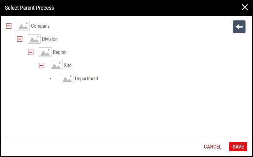
This Getting Started tutorial assumes an existing hierarchy design, which you may not have, and may not want, in your Enact system. The default Enact hierarchy looks like this:
This tutorial expects the following hierarchies:

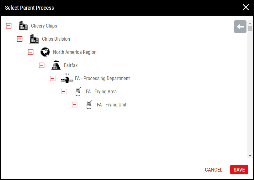
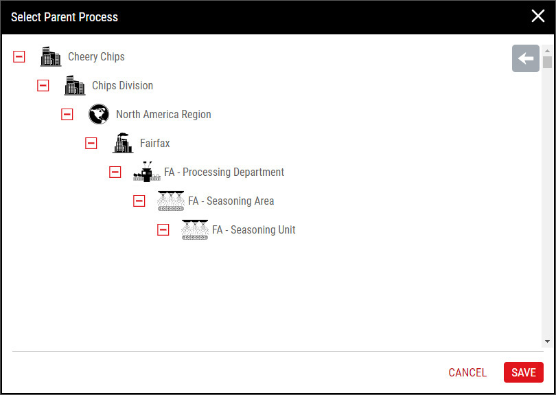
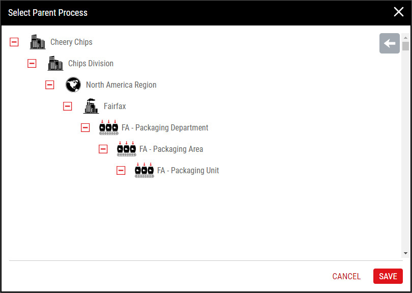
To match the expected hierarchy, please add the following:
- Slicing. Cheery Chips > Chips Division > North America Region > Fairfax > FA - Processing Department > FA - Slicing Area > FA - Slicing Unit
- Frying. Cheery Chips > Chips Division > North America Region > Fairfax > FA - Processing Department > FA - Frying Area > FA - Frying Unit
- Seasoning. Cheery Chips > Chips Division > North America Region > Fairfax > FA - Processing Department > FA - Seasoning Area > FA - Seasoning Unit
- Packaging. Cheery Chips > Chips Division > North America Region > Fairfax > FA - Packaging Department > FA - Packaging Area > FA - Packaging Unit
For more information, please see Creating Processes.
- Select Access Menu and then select Process | Processes.
-
To add the FA - Slicing Line 001 process, select Create Process, and then do the following:
- Short Name: FA - Slicing Line 001
-
Image: FASlicingLine001.png
How do I select the image?
In the Image section, select More, select Upload Image, browse to the desired image, and then select Open.
-
Parent Process: FA - Slicing Unit
How do I select the parent process?
Select Parent Process, select the desired parent process, and then select Save.
Select Save & Close.

My Processes
- Select User Settings and then select My Processes.
- In the My Processes dialog box, select FA - Slicing Line 001, and then select Save.

Code Groups
- Select Access Menu and then select Feature | Code Groups.
-
In the Code Groups landing page, select Create Code Group.
- In the Code Group data field, type Slice Inspection, and then select Save.
- Select Code, and in the Code Name data field, type Broken, and then select Save & Create Another.
- In the Code Name data field, type Discolored, and then select Save & Create Another.
- In the Code Name data field, type Perforated, and then select Save & Create Another.
- In the Code Name data field, type Wedged, and then select Save.
- Select Close.

Features
- Select Access Menu and then select Feature | Features.
-
To add Slice Thickness, select Create Feature, and then do the following:
- Short Name: Slice Thickness
-
Image: SliceThickness.png
How do I select the image?
In the Image section, select More, select Upload Image, browse to the desired image, and then select Open.
- Type: 1 - Variable
Select Save.
-
To add Slice Inspection, select Create Feature, and then do the following:
- Short Name: Slice Inspection
-
Image: SliceInspection.png
How do I select the image?
In the Image section, select More, select Upload Image, browse to the desired image, and then select Open.
- Type: 2 - Defect
-
Code Group: Slice Inspection
How do I select the code group?
In the Code Group drop-down list, select the desired code group. Hint
Select Save.

Next Step: Specification Limits (Slicing)